Spiral Top-loading of a Short Vertical
- Copyright (c) Ralph Holland VK1BRH 1995, Copyright (c) Amateur Radio 1995.
Introduction
Top-hat capacitance and inductive base-loading and centre-loading have traditionally been employed to bring short antennas to resonance; these methods are covered in detail in the literature [1, 2]. This article describes how the self-capacitance and inductance of a spiral coil can be employed as a top-loading element for a short vertical, with the obvious extension to end-loading of dipoles.
Construction
A spiral coil was constructed on a form composed of 69mm OD plastic drain-pipe and 15 plastic radials. The plastic radials are 7.9mm OD tubes used as uprights for small sprays, they are cheap and readily available from garden supply shops. One end of the upright is terminated with a screw thread, which can be tapped into the 69mm OD drain-pipe if suitable undersize holes are drilled (evenly) around the circumference of the drain-pipe.
The coil was wound from 0.6mm enamelled copper wire, from the junk-box. The wire was alternated over the radials in a basket-weave fashion. There must be an odd number of spokes to perform a basket weave! This resulted in a very neat and high Q coil. It should also be possible to stabilize the coil and remove the radial supports for even higher Q's.
The drain-pipe former was centered at the top of the 1.5m vertical via a wooden insert. The inner-end of the spiral coil was clamped to the top of the radiator. The 1.5m vertical had a 1m square ground mat and was connected to an elevated ground system to stabilize measurements.
The computer simulations were performed for unloaded 1.5m and 10m monopoles with 4 * 0.2 wave radials (at the various simulation frequencies) elevated 3m above the typical clay ground with a relative dielectric constant of 15 and conductivity of 5 milli-Siemens (15K,5mS) [5], the results were extrapolated to loaded antennas.
Results
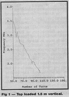
Starting from an initial one hundred turns on the top loading coil, the resonant frequency was determined with a grid-dip meter coupled into a half-turn loop connected between the radiator and the ground mat. The dip frequency was read from the dial of a digital communications receiver and recorded. One turn was removed from the top loading coil and the process was repeated.
Figure 1.0 shows how the spiral loading reduces the natural resonant frequency of the vertical.
 |
 |
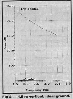
Figure 2.0 compares a 1.5m spiral-top-loaded antenna against an unloaded antenna over ideal ground. The losses are due to the RF resistance of the coil. The loss resistance of the coil and antenna was calculated as 29.8 ohms at 1.68 MHz decreasing to 19.6 ohms at 3.5 MHz .
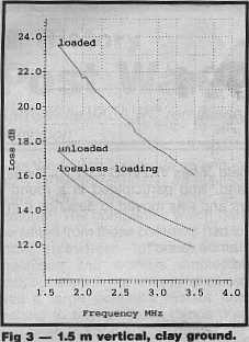
Figure 3.0 compares the same antenna over typical clay soil (15K, 5mS). The calculated total loss ranged from 24.7 at 1.68 MHz to 17dB at 3.5 MHz (4.1 - 2.8 S-points loss).
 |
 |
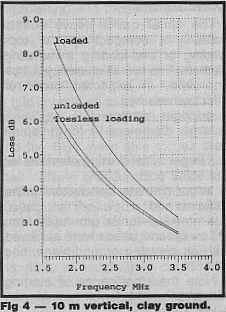
Figure 4.0 shows the vastly improved situation ( 1.5 - 0.6 S-points loss) when the radiator is lengthened to 10m, for the same ground.
Assumptions
Figure 2.0 was derived from the following:
- Radiation resistance. The current amplitude for the radiator was assumed
to be almost uniform over the entire vertical section due to the top loading
and the fact that power is lost in the loading coil. The loading and loss
would result in a travelling wave, rather than a standing wave. The radiation
resistance was calculated from the approximation: Rr = 80 * pi**2 * (Iav/Io)**2
- 2h ** 2 attributed to Kraus equation 5-3-14 [4] (2h is the length of
a. Rr = 1579.1 * h * h - for uniform current (h in wavelengths).
b. Rr = 789.6 * h * h - for sinusoidal current,
c. Rr = 394.8 * h * h - for triangular current.
- The coil current was assumed to be near sinusoidal. The coil RF resistance was calculated from the RF resistance of round copper wire [6] multiplied by the length of the wire in the spiral-loading coil. The assumed sinusoidal current taper requires this value to be divided by two as the average value of the current distribution is equal to the peak current divided by the square root of two.
- The coil was assumed to loose power through heating of this RF resistance, no attempt was made to quantify the amount of radiated power contributed by the coil - which may have some significance.
Figure 3.0 was derived from Figure 2.0 calculations and the additional ground losses were derived from computer simulations of elevated groundplanes [4].
Figure 4.0 is based on 0.18 lambda of spiral coil and radiator (the shortening factor observed in the 1.5m antenna) with ground losses simulated for ground parameters (13K,5mS).
Conclusion
The spiral basket-weave coil is certainly a compact way of top-loading or end-loading a radiating element. The overall efficiency will be improved, in expected order of effectiveness by:
- a longer radiator,
- larger diameter wire for the spiral coil,
- a larger initial starting diameter for the spiral coil,
- larger diameter conductor for the radiator,
- a more substantial ground system.
Low ground losses can be achieved with an elevated ground-plane, see reference [6].
Note, the loading coil may be radiating power - which could result in elliptical polarization (vertical from the monopole and horizontal from the coil); I suspect this would be the case when the coil resistance is lowered. Note the significance of starting with a reasonable length radiator or lower loss coil.
References
- Optimum Design of Short Coil-Loaded High Frequency Mobile Antennas, Bruce F. Brown. The ARRL Antenna Compendium Volume 1 page 108. Publisher: ARRL 1985.
- The ARRL Antenna Handbook, 15 Edition, page 16-5. Publisher: ARRL, 1988.
- The ARRL Antenna Handbook, 15 Edition, "Raditaion Resistance", page 2-34. Publisher: ARRL, 1988.
- http://www.amazon.com/exec/obidos/ASIN/0070354227/o/qid=912214947/sr=2-1/002-2869831-2020803 Antennas, John D. Kraus. Second Edition, page 217. Publisher: McGraw Hill 1988.
- http://www.amazon.com/exec/obidos/ASIN/0471585513/qid=912218966/sr=1-3/002-2869831-2020803 Fields and Waves in Communication Electronic, Simon Ramo, John R. Whinnery and Theodore Van Duzer. Publisher: John Wiley and Sons. First Edition 1965, page 295; Third Edition 1983, page 180.
- Short Vertical Antennas and Ground Systems - VK1BRH, Ralph Holland, Amateur Radio, Journal of the Wireless Institute of Australia, Vol 63 No 10, 1995, page 9.
* Terms
This article was first published in Amateur Radio Volume 63 No 10, October 1995 which is the journal of the Wireless Institute of Australia. Both the author and the WIA hold copyright. No reproduction is permitted for commercial purposes without express permission of the copyright holders.
(C) Copyright, Ralph Holland - VH1BRH 1995, 2004.
