Hybrid Antennas
Copyright (c) Ralph Holland VK1BRH Jan 1997, Copyright (c) Amateur Radio Jan 1997.[1]
Introduction
Hybrid antennas are composed of elements that emit a mixture of horizontal and vertical polarisation. Radiation from these antennas has different mixtures of horizontal and vertical polarisation at different azimuth and/or elevation angles. Hybrid antennas have been reported to have a tendency towards omni-directional radiation patterns.
This article presents computer simulations of some simple hyrid antennas.
Simulation Parameters and Graphs
The simulations were performed by NEC-2 (Ref 1) for antennas composed of 1.22mm lossless wire elements at 14 MHz above average ground and sea water. Two ground parameters were specified for the simulations: relative dielectric constant and conductivity in milli Seimens per metre; these are represented (in that order) in enclosed square-brackets. Eg [13,5] represents average clay soil, while [80,5000] represents sea water (Ref 2).
The graphical results show radiation efficiency and feedpoint impedances for various displacements; displacement is the term used for the distance between the lowest point of the driven element and the ground.
In addition three-dimensional antenna radiation patterns have been plotted for the total gain, which involves the summation of the response to both horizontally and vertically polarised signals. This gives a realistic indication of the h.f. antenna performance, as ionospheric propagation causes mixed polarisation. The graphs show the gain between 90 and 10 degrees elevation (inclusive), in steps of 10 degrees, across the full range of 0 to 360 degrees of azimuth, in 5 degree increments.
Half-wave sloping dipole (sloper)
The basic half-wave sloper is a half-wave dipole inclined 45 degrees to the ground and is probably the simplest of all the hybrid antennas. When the sloper is fed in the centre its feedpoint resistance is greater than 75 ohms. This antenna has been reported as having a near-omni-directional radiation pattern based on measurements by several authors (Ref 3).
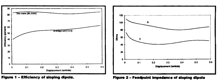
Figure 1 shows the efficiency of a sloping dipole as the displacement is varied.
Figure 2 shows the feedpoint impedance of the sloper versus the displacement for average ground [13,5]. Notice that it is quite inductive and hence can be shortened, with consequent reduction in feedpoint resistance.
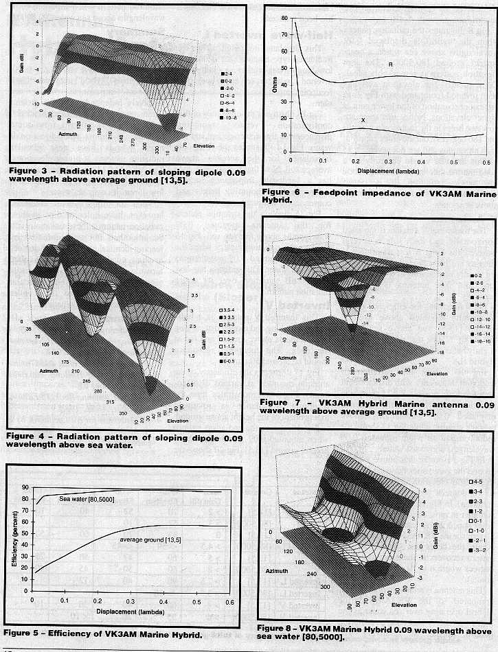
Figure 3 illustrates the radiation pattern for the sloper displaced 0.09 wavelengths above average ground [13,5].
Figure 4 illustrates the radiation pattern for the sloper displaced 0.09 wavelengths above sea water.
The VK3AM Marine Hybrid
This antenna is a bent half-wave dipole (Ref 4). The driven element is shaped like an L, with each side being one quarter of a wavelength. The antenna is oriented so the end of the bottom of the L points to 0 degrees azimuth (ie lies on the X axis), the remainder is vertical.
Figure 5 illustrates the radiation efficiency over average ground [13,5] and sea water [80,5000] at 14 MHz.
Figure 6 demonstrates the variation of the feedpoint impedance with displacement for average ground [13,5]. The initial peak in the feedpoint resistance is almost eliminated when simulating over sea water and the resistance and reactance were substantially the same as the poorer ground.
Figure 7 illustrates the radiation pattern, for the hybrid at 0.09 wavelengths displacement for average ground [13,5]. Note that there is a severe hole in the pattern centred around 180 degrees azimuth. The hole is on the left-hand-side looking directly at the L. This hole, although it is reasonably severe, probably is not as bad as it looks, because at 10 degrees elevation the pattern recovers with -5 dBi gain.
Figure 8 illustrates the radiation pattern when the hybrid is displaced 0.09 wavelengths above sea water, a near-perfect ground [80,5000]. The low elevation pattern is remarkably ideal. Consequently the elevation axis has been inverted (compared with Figure 7) to prevent obscuration of the lower gain at higher elevations. Notice that there are now two holes in the radiation pattern (0 and 180 degrees); but the holes appear at high elevations and are not severe.
This antenna would certainly be a good marine antenna since it has good low angle radiation, it is omni-directional, and is reasonably efficient above sea water.
V Antenna
The traditional V antenna is mounted horizontally and each side is several wavelength long. A less traditional V antenna has been modelled where each leg is only one quarter of a wavelength long and this antenna is mounted vertically.
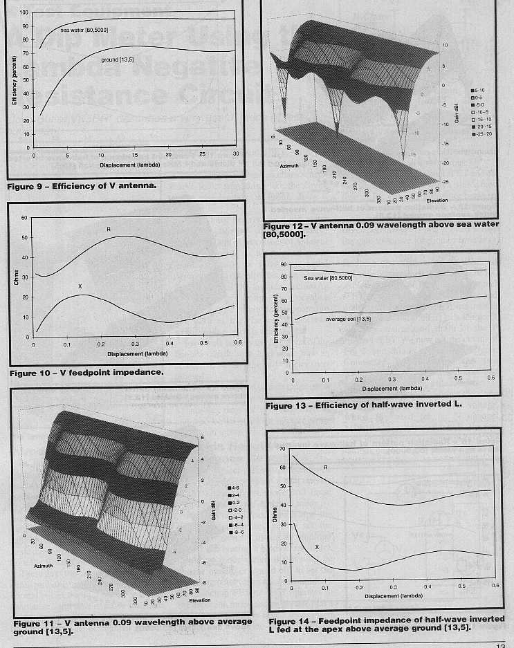
Figure 9 illustrates the efficiency of the V antenna mounted above average ground [13,5] and above sea water [80,5000]. Notice that this antenna has slightly better efficiency than the Marine Hybrid (L).
Figure 10 shows the variation of feedpoint impedance with displacement above average ground.
Figure 11 shows the radiation pattern for the antenna displaced 0.09 wavelengths above average ground, while Figure 12 shows the radiation pattern when mounted 0.09 wavelengths above sea water.
In Figure 11 notice that above average ground the gain varies between 5 dBi to -6 dBi from elevation angles of 90 down to 10 degrees (less than 2 S-points variation).
In Figure 12 notice that the gain is higher at most elevations, except two holes appear in the same fashion as the pattern for the VK3AM Marine Hybrid. Again the holes are severe, but the pattern recovers at the elevation of 10 degrees were it is 10 dB down (1.7 S-points).
This antenna is relatively poor for DX compared to the VK3AM Marine Hybrid operating over sea water as the holes in the V antenna's radiation pattern appear at relatively low elevations and the gain at low elevations has been reduced
Half-wave Inverted L
This simulated inverted L is not the traditional-type antenna that is used on low-bands but rather a half-wave inverted L which is fed at the apex. The feedpoint impedance will be close to 50 ohms.
Figure 13 illustrates the efficiency of this configuration versus mounting displacement above average soil and sea water.
Figure 14 illustrates the feedpoint impedance for the antenna above average soil. Note that this antenna too has a feedpoint impedance largely independent of mounting height and consequently soil parameters.
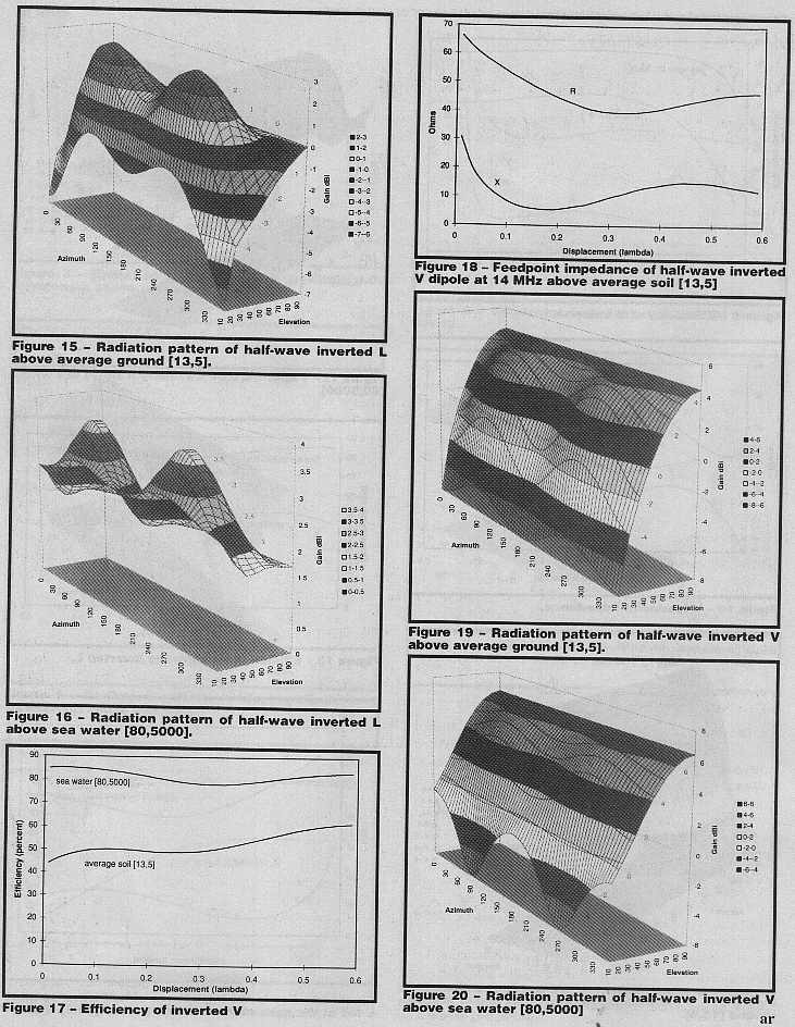
Figure 15 displays the radiation pattern for the antenna mounted 0.09 wavelengths above average soil.
Figure 16 displays the radiation pattern when the antenna is mounted 0.09 wavelengths above sea water. This antenna has less than 3 dB variation over its entire radiation pattern.
Inverted V
This inverted V antenna is a half-wavelength long and mounted at varying displacements above ground and fed at the apex. The feedpoint resistance should be around 50 ohms.
Figure 17 illustrates the efficiency of the antenna mounted at various displacements.
Figure 18 demonstrates how the feedpoint impedance is relatively independent of the height above ground.
Figure 19 shows the radiation pattern when mounted 0.09 wavelength above normal ground [13,5]
Figure 20 shows the radiation pattern when mounted 0.09 wavelengths above sea water [90,5000].
Summary
A summary of the total gain patterns has been provided in Table 1.
| Antenna |
Ground |
Max Gain dBi |
-3dB Elevation |
-6dB Elevation |
-9dB Elevation |
-12dB Elevation |
| Sloper | [13,5] |
>2 |
70 |
52 |
40 |
10 |
| Sloper | [80,5000] |
>3 |
57 |
10 |
||
| VK3AM L | [13,5] |
0 |
85 |
70 |
60 |
50 |
| VK3AM L | [80,5000] |
>4.5 |
<=30 |
<=45 |
||
| V | [13,5] |
>5 |
60 |
47 |
40 |
20 |
| V | [80,5000] |
>8 |
60 |
50 |
45 |
40 |
| Inverted L | [13,5] |
>2.5 |
90 |
40 |
12 |
|
| Inverted L | [80,5000] |
>3.5 |
<=10 |
|||
| Inverted V | [13,5] |
>4 |
60 |
40 |
30 |
10 |
| Inverted V | [80,5000] |
>6 |
55 |
20 |
<10 |
Table 1 - Summary of total gain
Conclusions
All these hybrid antennas have feedpoint impedances which are relatively independent of the ground parameters and mounting height.
The radiation pattern from some hybrids are almost omni-directional; most hybrids have near circular radiation patterns at higher elevations. The VK3AM Marine Hybrid and the Inverted L have good performance at low elevations over sea water.
Most of the hybrid antennas, however, have holes or dips in their radiation patterns; these variations can be smoothed out or eliminated by feeding identical elements at 90 degrees in phase quadrature (commonly called turnstile configuration). Such turnstile antennas will exhibit circular polarisation throughout their entire hemi-spherical radiation pattern.
References
- Computer program NEC-2, G. J. Bourke, Lawrence Livermore National Laboratory, 1984.
- Short Vertical Antennas and Ground Systems, Ralph Holland, Amateur Radio, October 95.
- The ARRL Antenna Book, 15 Edition, Publisher: ARRL, 1988.
- Hf Antennas for All Locations, by L. A. Moxon, G6XN, on page 154, publisher RSGB.
* Terms
This article was first published in Amateur Radio Volume 65 No 1, January 1997 which is the journal of the Wireless Institute of Australia. Both the author and the WIA hold copyright. No reproduction is permitted for commercial purposes without express permission of the copyright holders.
This HTML document was converted from Microsoft Word format by www.gatech.edu GT_HTML 6.0d 10/03/1997 8:46PM.


