Horizontal Half-wave Dipole Above a Counterpoise
- Copyright (c) Ralph Holland VK1BRH 1996, Copyright ( c)Amateur Radio 1996.
Introduction
All antennas that are situated close to the ground are affected by that ground to some extent.
The most obvious effect is that the ground forces the antenna's radiation pattern to appear in the half-space above the ground. This is illustrated by comparing the radiation around a monopole fed against ground to that of a dipole in free-space. The monopole has twice the power in the hemisphere above the ground compared with the power in either hemisphere of symmetry for the dipole in free-space. The nature of this reflection of energy above the ground is governed by the polarisation of the antenna and the ground effectiveness. The dielectric constant and conductivity of the ground determines how well the ground acts as a conductor and hence a reflector.
A less obvious effect is that the ground absorbs energy from the antenna; this energy is wasted in the ground's intrinsic resistance (Ref 3).
The placement of an artificial ground, or counterpoise, can decrease the ground losses and enhance the performance of a horizontal antenna. The enhancement can be investigated by performing comparative measurements of the feedpoint resistance or by performing computer simulations.
This article is based on computer simulations using NEC-2 (Ref 1) for antenna systems at 1.825 MHz over average ground with a relative dielectric constant of 13 and conductivity of 5 milli-Seimens per metre [13,5]. The simulations were performed for ideal (lossless) antenna elements with a diameter of 1.22 milli-metres.
Terminology
Displacement is the term used for the distance between the counterpoise (which is the antenna system's lowest element) and the ground. Separation is the term used for the distance between the driven-element and the counterpoise. Displacement, in the regular dipole case, is the distance between the dipole and the ground.
Results
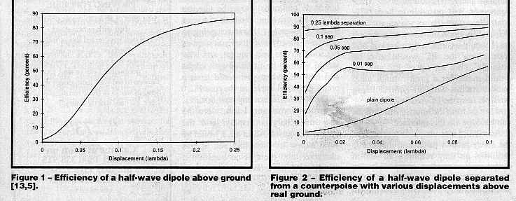
Figure 1 illustrates the efficiency of the horizontal half-wave dipole at various displacements. In general, the efficiency improves as the dipole is raised higher. Note that 100 percent efficiency is not achieved at a quarter wavelength displacement because, even at this height, the ground has introduced some losses into the antenna system.
Figure 2.0 illustrates the efficiency for various counterpoise systems and a dipole above ground. Notice that there is a knee in the counterpoise curves, which indicates that there is an optimum displacement. Be careful when interpreting the graphs, increasing the separation suffers from the law of diminishing returns; the efficiency of a counterpoise system must be compared with that of a dipole at the same equivalent height, ie. the counterpoise displacement plus the driven element separation. Observe how a counterpoise improves the efficiency of a horizontal antenna system.
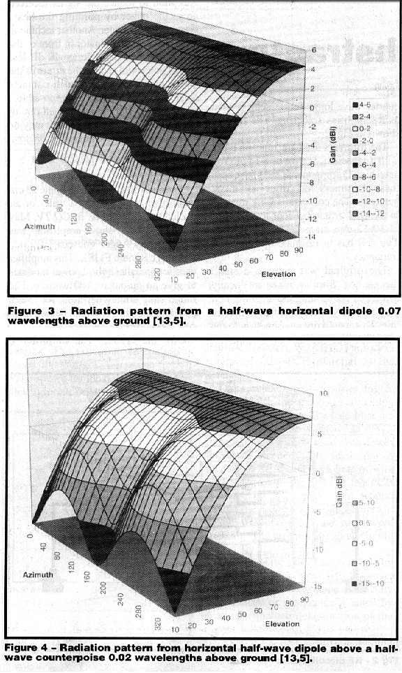
Figure 3 shows the radiation pattern of a horizontal dipole displaced 0.07 wavelengths above ground.
Figure 4 shows the radiation pattern of a dipole offset by 0.05 wavelengths above a counterpoise that is displaced 0.02 wavelengths above the ground (same equivalent height as the dipole only system).
The horizontal dipole system has a minimum gain of 0 dBi at 51 degrees elevation, while the counterpoise system has a minimum gain of 0 dBi at about 42 degrees of elevation. Alternatively, antenna gain comparisons at all elevation angles show that the counterpoise gain is greater than the dipole system by 2.53 ( 0.05 dB. This demonstrates that the counterpoise is a more effective ground system; the counterpoise reflects more energy into the half-space so less is wasted in the intrinsic ground resistance and more is radiated.
Conclusions
The placement of a counterpoise below a horizontal antenna can improve the antenna efficiency by a reasonable amount. The effect under a horizontal antenna is similar to the effect of elevated ground-planes for vertical antennas (Ref 2). You can measure this effect by observing an increase in field strength or by observing the lowering of your feedpoint resistance when adding the counterpoise (Ref 3).
At 160m, with ground parameters [13,5], the effect peaks with counterpoise displacements of about 0.02 wavelengths above the ground.
Increasing the antenna system efficiency with a counterpoise increases the gain at all angles, effectively lowering the effective radiation angles.
References
- Computer program NEC-2, G. J. Bourke, Lawrence Livermore National Laboratory, 1984.
- Short Vertical Antennas and Ground Systems - VK1BRH, Ralph Holland, Amateur Radio, October 95.
- Horizontal Antennas above Real Ground, Ralph Holland, Amateur Radio, October 1996
* Terms
This article was first published in Amateur Radio Volume 64 No 11, November 1996 which is the journal of the Wireless Institute of Australia.
Both the author and the WIA hold copyright. No reproduction is permitted for commercial purposes without express permission of the copyright holders.
This HTML document was created by www.gatech.edu GT_HTML 6.0d 09/03/1997 12:55 AM.


