How to fly an NDB
Introduction
It is advantageous to understand how both an Non Directional Beacon and Automatic Direction Equipment work when appreciating how to fly using an NDB and ADF.
NDB
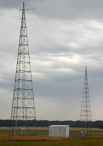
An Non Directional Beacon is comprised of an omni-directional Vertically polarised (usually capacitively top-loaded) antenna at a known stationary location coupled to a Medium to Low Frequency Transmitter that has an amplitude modulated identification of one, two or three-letter Morse Code callsign. In Australia they use the three-letter Airport Code when located at an airport.
The NDB is described in ICAO Annex 10 that specifies that NDBs operate between 190 kHz and 1750 Khz, as a consequence an ADF may receive AM broadcast stations when you place the ADF into receive only mode, or a known broadcast station may be used for homing and fixing, and for these purposes some AM broadcast frequencies are listed in the ERSA.
There are a few types of NDBs:
- En route used to mark airways for homing etc
- Approach NDBs that have a hold and approach associated with them
- Localiser beacons for guidance to an ILS
- Locator beacon for guidance to an ILS
- some AM broadcast stations that may consequently be used in navigation
ADF
The Automatic Direction Finding equipment is a form of Radio Compass that provides the pilot with a relative bearing of the NDB. The needle will point to the beacon with the aircraft nose being straight ahead.
A radio wave consists of two electromagnetic components; an electric field (E-field) and a magnetic field (H-field) that are orthogonal to each other in space, and their amplitudes vary sinusoidally with time. The E-field of an NDB antenna is vertically oriented perpendicular to the ground, and the H-field is oriented horizontally parallel to the ground.
The ADF system contains a loop antenna where the H-field induces signals, and a sense antenna that has signals induced by the E-field (The sense antenna is either a wire or a short antenna in the same housing as the loop antenna e.g. in a KR-87 antenna housing).
The KR87 loop antenna consists of two mutually perpendicular coils on a square ferrite core. The axis of one winding is aligned along the longitudinal axis of the aircraft and the voltage induced in the coil is the sine of the angle between the nose of the aircraft and the beacon antenna. The other coil winding is aligned laterally to the aircraft (i.e. parallel to the wings) and the voltage induced in it is the cosine of the relative bearing between the nose of the aircraft and the beacon.
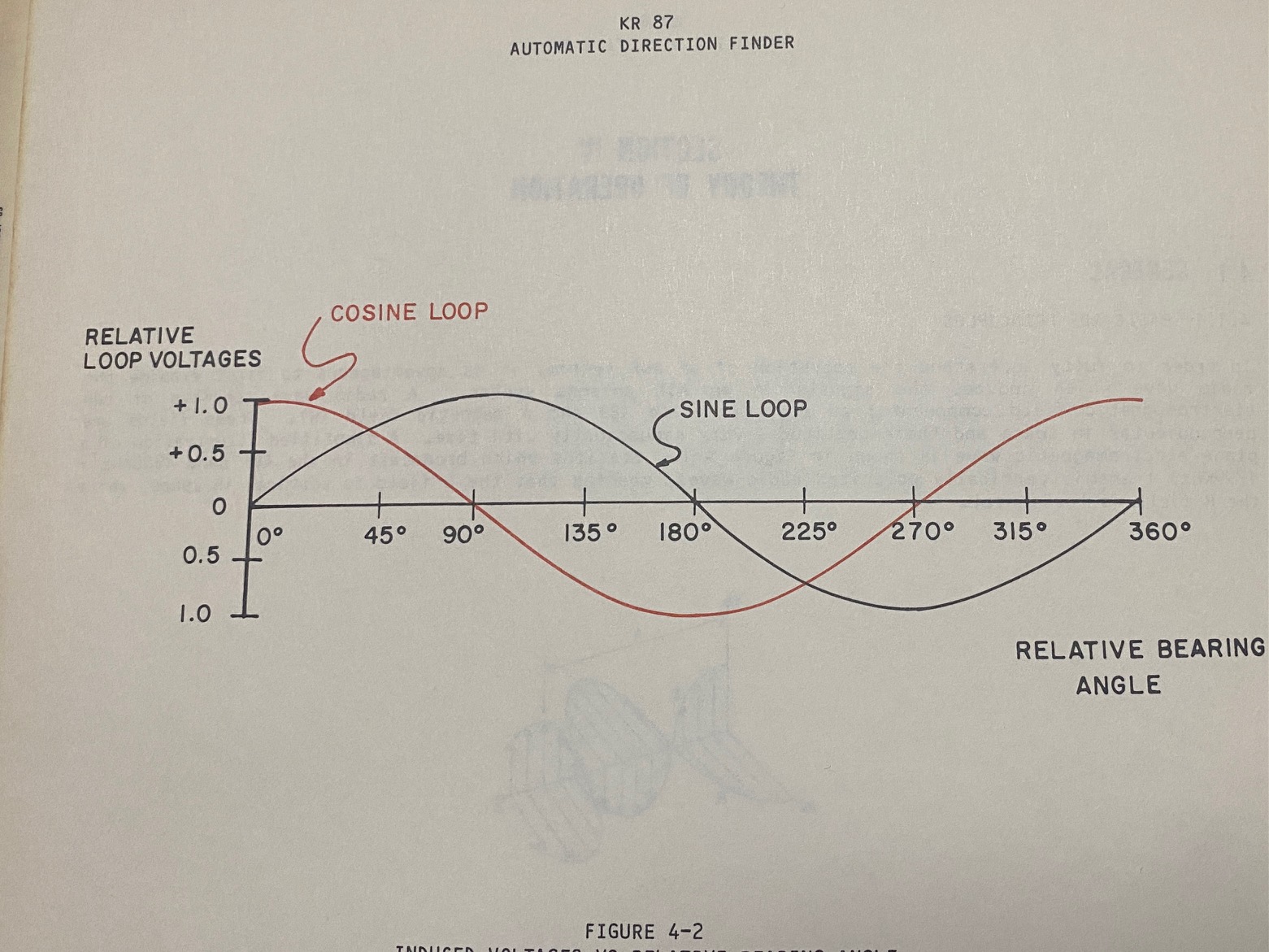
The KR87 uses a sense antenna with phase correction to provide disambiguation of the correlation of equal sine and cosine curves at 45 degrees and 225 degrees relative bearing. These sine and cosine signals are demodulated via a balanced demodulator (switched at 32 Hz - the hum you can hear) and summed with the sense antenna signal that is in phase quadrature with the demodulated loop antenna signals. This summation of three signals results in a quadrature signal that provides the relative angle to the station.
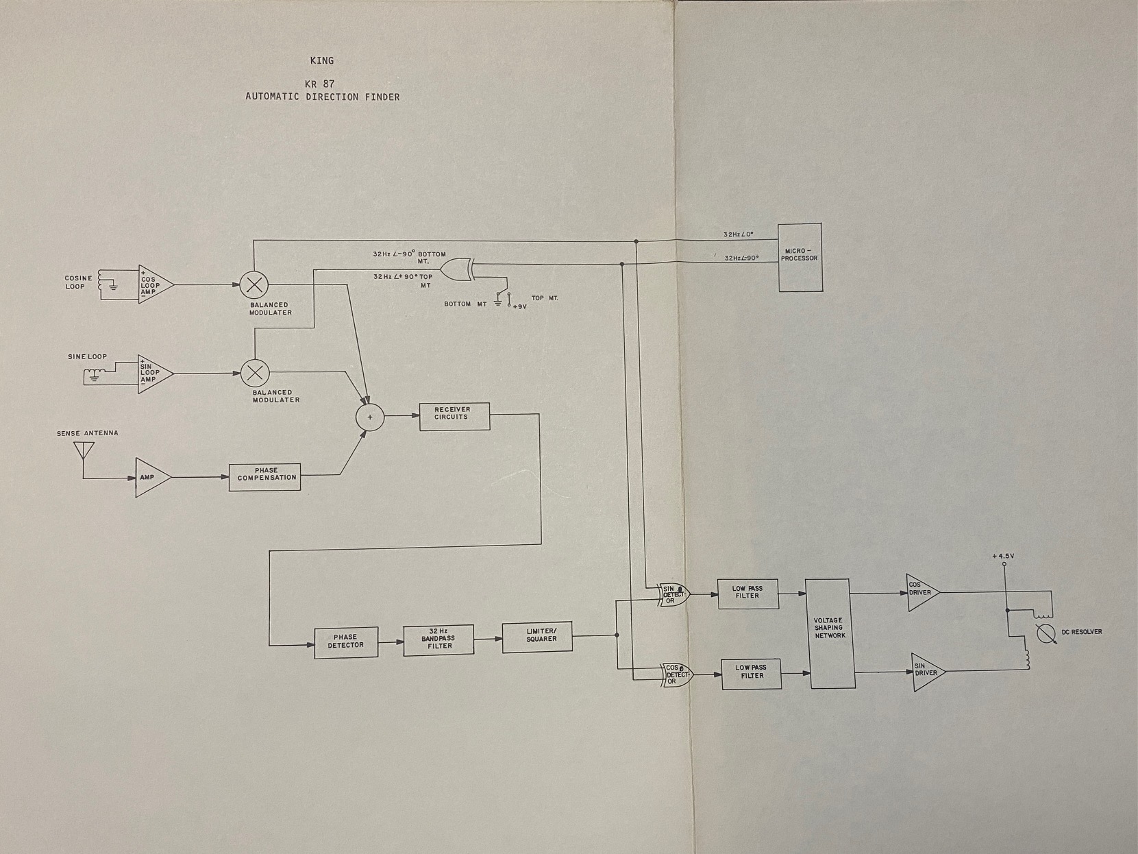
The signals are integrated to produce two D.C. analogue voltages to drive the indicator needle in the resolver. The needle of the resolver indicator thus will provide a bearing relative to the aircraft nose.
limitations
NDB ADF bearings are subject to limitations.
quadrantal error
Since the laterally oriented coil is along the axis of the wings, its response is subjected to errors caused by the angle of bank. This is commonly referred to as quadrantal error, however, any error in a quadrant sense is quadrantal error and may actually be caused by aircraft antenna installation and structure, besides just banking the aircraft.
The maintenance manual states that there are adjustments in the receiver to correct the quadrantal "out-of-round" errors - however they cannot adjust out errors caused by bank angles as there are no gyroscopic inputs into the KR87 ADF, nor most others ADF that I am aware of. (In a typical Mooney installation the quadrantal error exceeds 17 degrees when the wing is banked, however there is also some quadrantal error in the forward sense approaching the aid and lessor in the rearward sense when leaving the aid - when the wings are level! This is because the ADF antenna is mounted rearward on the emmpenage way behind the rear seats and hence suffer from reflections of the wing in the forward bearing direction, but no reflections in the rearward bearing. Banking makes this reflection even worse)
Australian and USA Automatic Direction Finding equipment are TSO-C41d with 1kHz steps (which is slightly different to DO-179 that provides for 0.5kHz tuning resolution in Europe)[1]
http://www.airwaysmuseum.com/NDB%20BLT%202-05.htm#
propagation
The NDB radio waves have two paths:
- along the ground - which may go beyond the line of site - termed ground-wave
- and ducting and reflection between the ground and the ionosphere - termed sky-wave or colloquially skip.
During the day the D-layer of the ionosophere attenuates the lower frequencies so it is unusual for sky-wave propagation to occur with NBD and Broadcast stations, but at night this layer is not present and signal can propagate over very long distances via ionspheric and ground reflections depending on the distance from the station and the details of the ionosphere. The mixing of ground-wave and sky-wave introduces amplitude, polarisation and phase variations that may affect the workings of an ADF receiver. This may result in erroneous readings.
The night time range of moderately powered NDB beacons is 60 miles over land and 100 miles over the ocean and beyond these ranges they will be subjected to propagation effects, particularly at night.
Low power beacons that only have a range of 30 miles or so are largely unaffected by ionospheric propagation.
Lightning
Lighting strikes can be both vertically and horizontal polarised depending on whether they are ground or inter-cloud strikes respectively, and are often produce broad frequency radio waves of such magnitude that they will temporarily cause the ADF needle to deflect from the relative bearing.
People say the needle will point to the storm, thus the accuracy of the ADF needle will vary when flyng near a storm.
co-channel interference
If a NDB is operating on the same of an adjacent frequency to another NDB then there are likely to be resolution errors in the relative bearing; these errors cannot be corrected or allowed for and it is important to understand what co-channel interference sounds like and its effects. The errors may be serious is the ADF is tuned to an NDB beyond it usable range. You must always check the integrity of the identification, the signal and the indicated relative bearing by some other means. (You could also tune to a strong broadcast station to roughly verify your position.)
mountain effects
If you are flying in or across mountainous terrain the ground reflections from the slopes of the hills can affect the polarisation and phase of the NDB signal. These other reflected signal mix with the ground-wave signal and introduce errors that vary of terrain and hence time. Bearings will be found to vary rapidly until the affected area is passed.
range
The range of an NDB is affected by the power of the transmitter and antenna system, and the terrain over which the ground-wave propagates, Lossy ground reduces the ground-wave propagation, where as highly conductive ground, such as swampy soil, or the ocean significantly increased the range of reception of an NDB.
The signal from and NDB also increases over unfavourable (poorly conductive soil) with aircraft height above ground.
back bearing
It is better to use the back bearing to an NDB that you have overly flown, and only tune to a forward facing NDB when about half-way on track as the back bearing will be superior.
homing
Homing is the procedure of placing the NDB relative bearing needle on the nose of the aircraft by changing the aircraft heading to keep the needle head on the nose of the aircraft.
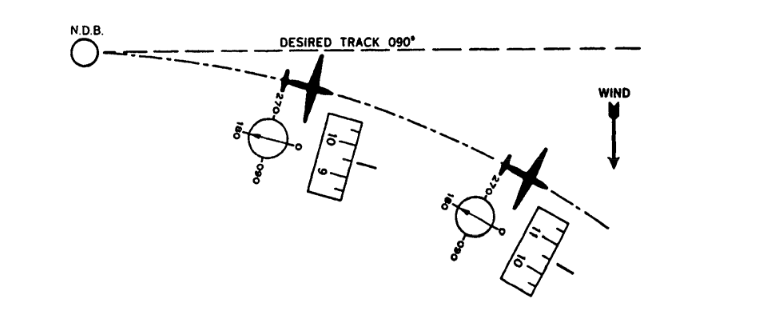
When there are crosswinds homing will result in a curved path, but it will always result in the aircraft flying towards the station with station passage almost guaranteed.
Station passage is indicated by the needle sweeping from pointing forward to pointing aft, and the closeness of passage is indicated by the speed of the needle transition. A good station passage occurs relatively quickly, whereas a poor passage passing abeam has the needle move more slowly as it points to the antenna passing to one side of the aircraft as the aircraft flies by.
track made good
A track-made good may be established by turning the aircraft into wind to counter the wind-drift such that the NDB needle relative bearing will correspond to the desired radial from or bearing to the aid, and the aircraft will track to or from the NDB along the radial.
The correction for wind-drift inbound is towards the wind by the wind correction angle and outbound away from the tail with twice the wind correction angle pointing the aircraft into wind. The head to the Navaid is blown towards the wind and the tail is blown away by the wind.
departure
Should the aircraft depart with constant relative NDB indication in wind then the aircraft heading will follow a curved path.
Should the aircraft depart with the desired heading set then the ADF needle will show a constant reading with the needle indicating the angle of drift.
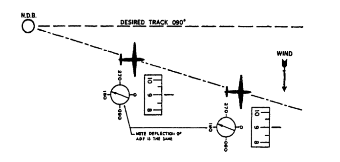
The correct procedure is to depart tracking away from the NDB allowing for drift - which is called back-tracking - something pilots did before magenta lines.

Intercepting
When an aircraft is not tracking to the desired bearing, or from a desired radial it must alter heading to intercept the desired track.
Tracking towards the station you set your heading bug to the desired bearing to the station and turn the aircraft heading past the bearing by 30 to 45 degrees to permit the head of the needle to fall onto the desired station bearing.
Tracking away from the station you set your heading bug to the desired radial from the station and you must turn the aircraft away from the tail past the desired radial to drag the tail onto the desired track. Depending on distance it may be necessary to perform a 30 or 45 degree intercept.
After the track has been intercepted, adjust the aircraft heading to maintain the Bearing to the station, or the Radial from the station following the #tracking procedures described below.
For some intercepts it may be necessary to arc around the aid at a constant distance in order to position for a satisfactory intercept. See the #arcing described later.
Tracking
Inbound: when you have the head of the needle pointing to the inbound bearing, if the head moves to the left (towards the edge of the 5 degrees) turn left to compensate, if the head moves right, turn right to compensate. If the drift away from the centre of the desired bearing is increasing then increase the turn in the same direction sense as the needle deflection from centre; if the correction is too much (needle going the other way) then halve the correction. If it is still drifting the other way, halve the correction again, or chase the needle head until you counter drift.
With wind, inbound you need to apply the Wind Correction Angle turning into the direction of the wind where WCA x in degrees is approximately the crosswind component / Ground Speed expressed as a ratio of x/60, to a max of 20 - 30 degrees, otherwise you should not be flying. Turning into wind via the WCA is the only way to counter the drift.
Outbound: when the tail of the needle deflects to the right of centre (of the radial), turn the aircraft left; if the tail of the needle deflects to the left of the radial, turn the aircraft to the right. If the tail does not rise quickly enough then turn more away from the tail in the direction you want the tail to rise to. If the tail begins rising quickly then halve the aircraft turn rate, if it is still rising then halve it again, or drag the needle where you want it to go by chasing it across the centre. Outbound is a lot easier than inbound because the aircraft distance from the station is increasing and the rate-of-change caused by a turn and wind-drift decreases providing more time for corrections.
With the wind outbound you need to turn the aircraft into wind to counter the drift of the tail from the center of the band of the desired radial (indication +/- 5 degrees).
On the outbound leg of a hold they say to turn 2 to 3 times the WCA into wind to allow room for the cross wind turn onto the inbound bearing. However, if you want to maintain the desired outbound radial for a procedure you must turn into wind by exactly the WCA to counter the drift of the needle, and then drag the needle to correct its drift to maintain the centre of the +/- 5 degrees of the radial from the station.
Recall that the Navaid is pointed to by the head of the needle.
Arcing
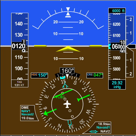
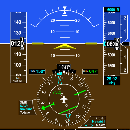
With the aircraft positioned some distance from the station turn the aircraft in the desired direction of the arc until the ADF needle is at 90 degrees (i.e. until the NAVAID station is off one wing tip).
With the heading bug and heading pointing 90 degrees off the needle maintain that heading until the tail rises by 10 degrees.
Then adjust the heading and bug by 10 degrees away from the tail and repeat the processes each 10 degrees of rise.
If the head is to the left wing you are arcing in a left-turn counter-clockwise, or obversely if the head is to the right then you are arcing in a right turn clockwise. The tail will always rise, and you always turn away from the tail to resume the 90 degree orientation with the NAVAID station i.e. the pilot flies with the station abeam.
Distance measuring equipment (such as a GPS way-point centred on the NAVAID) may be used to ensure that the arc is circular, by observing the distance to the Navaid. If the aircraft is closing the distance then the pilot can turn away from the station towards the outside of the arc. If the distance to the station is increasing then the pilot can turn the aircraft towards the station.
To adjust the distance and then adjust the heading to have the NAVAID abeam and repeat the process each time the tail rises until the aicraft can intercept the desired inbound bearing or outbound radial.
An arcing approach is a type of instrument approach where the aircraft flies a set radius around the NAVAID in order to intercept a final approach course inbound. The basic procedure is fly 10, twist 10 degrees.
NDB arcing is very similar to How to fly a VOR.

