How to fly an NDB
Introduction
It is advantagous to understand how both an Non Directional Beacon and Automatic Direction Equipment work when appreciating how to fly using an NDB and ADF.
NDB
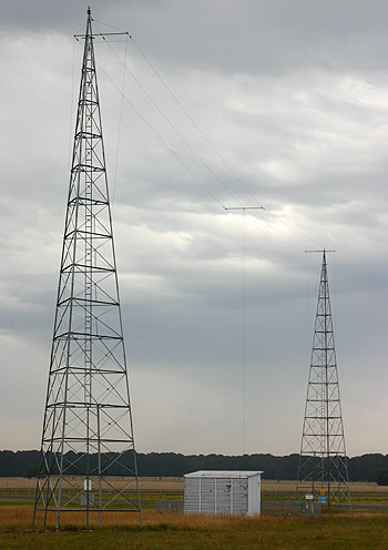
An Non Directional Beacon is comprised of an omni-directional Vertically polarised (usually capacitively top-loaded) antenna at a known stationary location coupled to a Medium to Low Frequency Transmitter that has an amplitude modulated identification of one, two or three-letter Morse Code callsign. In Australia they use the three-letter Airport Code when located at an airport.
The NDB is described in ICAO Annex 10 that specifies that NDBs operate between 190 kHz and 1750 Khz, as a consequence an ADF may receive AM broadcast stations when you place the ADF into receive only mode, or a known broadcast station may be used for homing and fixing and for these purposes some AM broadcast frequencies are listed in the ERSA.
There are a few types of NBs:
- En route used to mark airways for homing etc
- Approach NDBs that have a hold and approach associated with them
- Localiser beacons for guidance to an ILS
- Locator beacon for guidance to an ILD
- some AM broadcast stations that may consequently be used in navigation
ADF
The Automatic Direction Finding equipment is a form of Radio Compass that provides the pilot with a relative bearing of the NDB. The needle will point to the beacon with the aircraft nose being straight ahead.
A radio wave consists of two electromagnetic components; an electric field (E-field) and a magnetic field (H-field) that are orthogonal to each other in space, and their amplitudes vary sinusoidally with time. The E-field of an NDB antenna is vertically oriented perpendicular to the ground, and the H-field is oriented horizontally parallel to the ground.
The ADF system contains a loop antenna where the H-field induces signals, and a sense antenna that has signals induced by the E-field (The sense antenna is either wire or a short antenna in the same housing as the loop antenna e.g. in a KR-87 antenna housing).
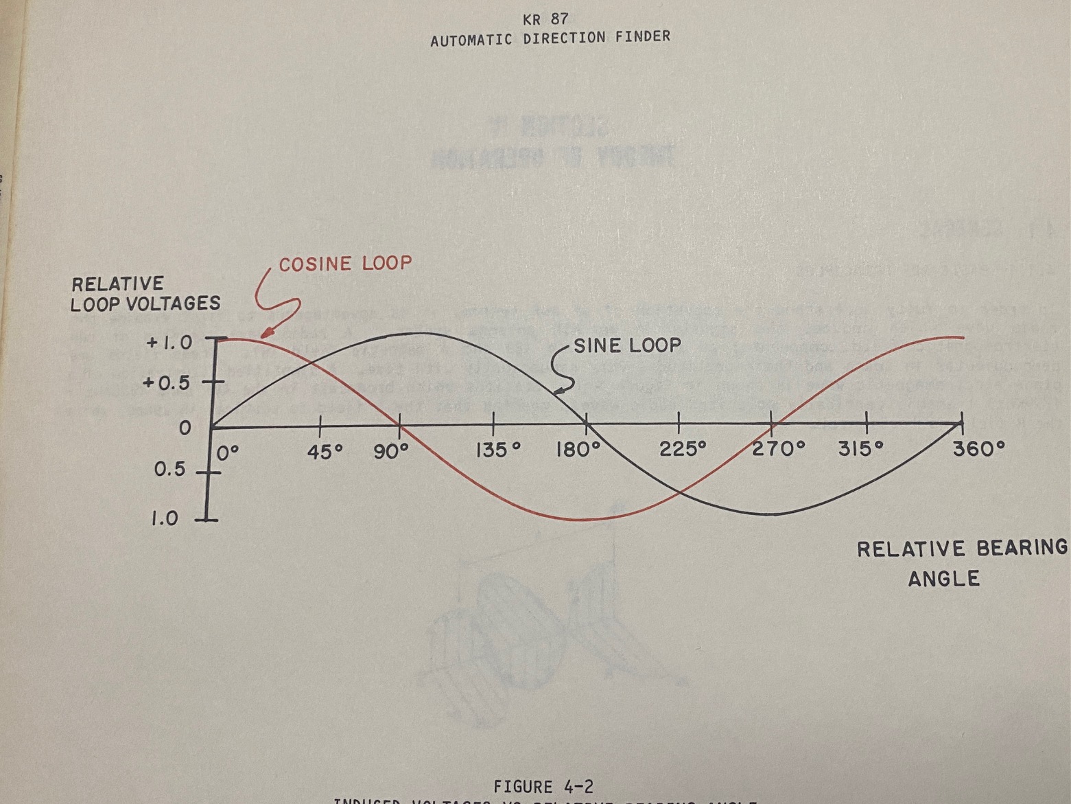
The KR87 loop antenna consists of two mutually perpendicular coils on a square ferrite core. The axis of one winding is aligned along the longitudinal axis of the aircraft and the voltage induced in the coil is the sine of the angle between the nose of the aircraft and the beacon antenna. The other coil winding is aligned laterally to the aircraft (i.e. parallel to the wings) and the voltage induced in it is the cosine of the relative bearing between the nose of the aircraft and the beacon.

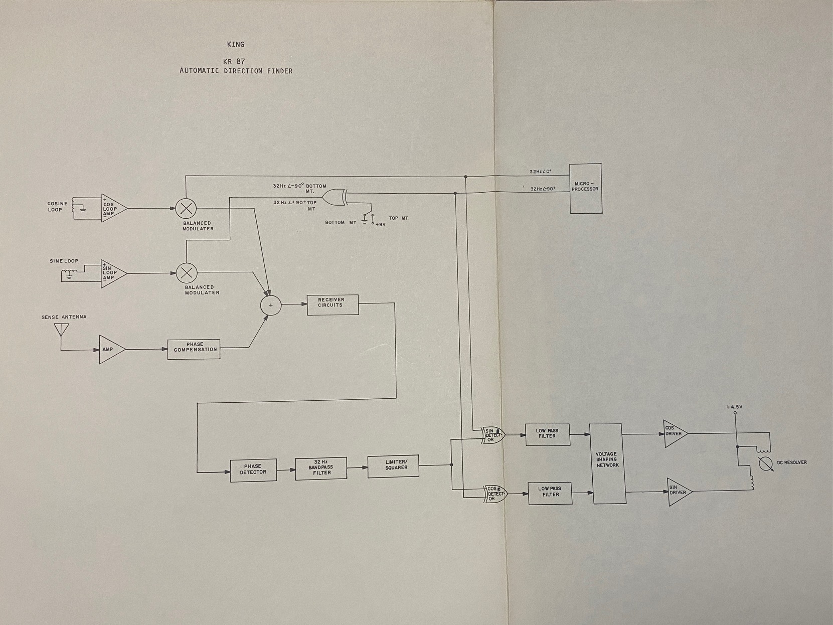
The KR87 uses a sense antenna with phase correction to provide disambiguation of the correlation of equal sine and cosine curves at 45 degrees and 225 degrees relative bearing. These sine and cosine signals are demodulated via a balanced demodulator (switched at 32 Hz - the hum you can hear) and summed with the sense antenna signal that is in phase quadrature with the demodulated loop antenna signals. This summation of three signals results in a quadrature signal that provides the relative angle to the station.

The signals are integrated to produce two D.C. analogue voltages to drive the indicator needle in the resolver. The needle of the resolver indicator thus will provide a bearing relative to the aircraft nose.
Since the laterally oriented coil is along the axis of the wings, its response is subjected to errors caused by the angle of bank. This is common referred to as quadrantal error, however, in the KR87 manual it lists any error in quadrant sense as quadrantal error and may actually be caused by aircraft antenna installation and structure. They have adjustments that may be used to correct the "out-of-round" errors - however they cannot adjust out errors caused by bank angles as there are no gyroscopic inputs into the KR87 ADF, nor most others that I am aware of.
Australian and USA Automatic Direction Finding equipment are TSO-C41d with 1kHz steps (which is slightly different to DO-179 that provides for 0.5kHz tuning resolution in Europe)[1]
http://www.airwaysmuseum.com/NDB%20BLT%202-05.htm#

