Horizontal Antennas Above Real Ground
* Copyright (c) Ralph Holland 1996, Copyright (c) Amateur Radio 1996.
Introduction
Antennas are influenced by the effect of the ground and by the type of conductors from which they are constructed. The feedpoint impedance is the summation of the radiator's self impedance, the mutual impedance of its image in the ground, and the loss resistance.
The loss resistance is the summation of the R.F. resistance in the conductor, and the resistance introduced by consumption of power in ground losses and other media close to the antenna. The conductor's resistance is modified by the skin-effect which causes the current to only flow in the outer parts, or skin, of the conductor. The effect causes the resulting resistance to increases in proportion to the square root of the frequency (see Table 1 and Table 2).
Horizontal antennas are subjected to the influence of a broadsize image in the ground. The antenna and its image are in anti-phase, so radiation tends to be cancelled at low angles and the radiation resistance is lowered because the mutual impedance of the image is subtracted from the self-impedance of the driven element.
Modeling
To quantify the effects of locating antennas above real ground, I have once again resorted to computer modelling using NEC-2 (Ref 1). All simulation results have been performed with 1.22mm diameter wire (SWG #18) and assume lossless conductors.
The simulation results are displayed graphically so you can determine the trends and evaluate your own antennas. The soil parameters for each simulation are enclosed in square brackets. For example, [13,5] represents ground with a relative dielectric constant of 13 and conductivity of 5 milli-Siemens / m (2S = 1/2ohm, while 4S = 1/4 ohm). The selected values are: [5,1] for poor soil, [13,5] for average clay soil, [20,30.3] for good soil and [80,5000] for sea water, which is very close to perfect.
Table 1 and Table 2 are included so you can evaluate conductor resistance losses due to the skin effect (Ref 2).
Results
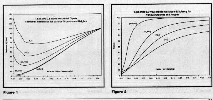
Figure 1 shows the effects of various types of grounds on a 1.825 MHz horizontal 0.5 wave dipole between 0.01 and 0.25 wavelengths above the ground. Note how over poorer soils the feedpoint impedance is dramatically higher than the resistance for perfect ground. Notice how the feedpoint resistance for a horizontal antenna becomes very low as the antenna approaches a perfect earth. (The feedpoint resistance of a perfect conductor over a perfectly conducting ground is the radiation resistance of the antenna.)
Figure 2 illustrates the overall antenna efficiency; a measure of how much power is radiated over the hemisphere, compared to power fed into the antenna (the missing power is absorbed by the ground).
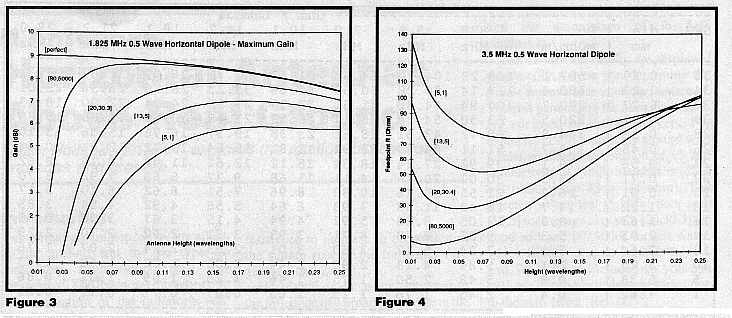
Figure 3 illustrates the effect upon the maximum gain. (However, at 160m, poor ground means the maximum gain is at an elevation of 90 degrees - ie straight up!)
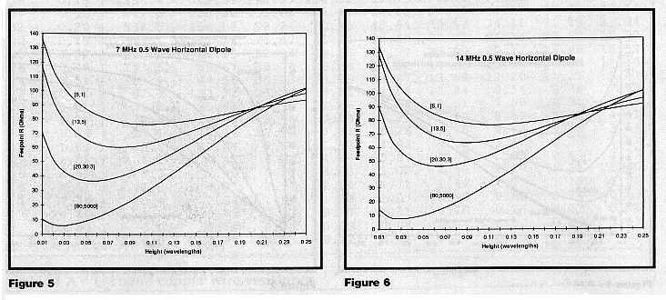
Figures 4, 5, and 6 show the effect upon feedpoint resistance at 3.5 MHz, 7.0 MHz and 14.0 MHz respectively.
Table 1 and Table 2 give the R.F. resistance of round copper wire at various frequencies. The values are listed in ohms per wavelength. You must halve these values for wires carrying cosinusoidal currents. The resulting value when added to the graphical results accounts for losses in a non-ideal conductor.
Conclusions
The radiation resistance of a horizontal antenna is lowered as the antenna is brought closer to the ground because self and mutual impedances subtract.
As a horizontal antenna approaches lossy media the feedpoint resistance rises due to increasing power losses in the media. You must be wary of this tendency for low antennas to apparently present a good feedpoint resistance.
Poor conductors, or inappropriate conductor sizes, will also introduce loss resistance. This effect is particularly noticeable in cases such as loading coils.
By comparison though, a horizontal radiator has less ground loss than a vertical antenna mounted at the same average height (compare the graphs for horizontals against those for verticals from Ref 3.0).
References
------------------------------------------
Ohm / Lambda--------------------
B&S dia | Dc. 1.825
3.5 7.0 10.1 14.2
18.1 21.2 29.0
AWG mm | mOhm/m MHz MHz MHz
MHz MHz MHz MHz
MHz
--------------------------------------------------------------------------
36 0.13 | 1356.4 329.59 195.37 114.92 89.43 71.08 60.62
54.77 44.84
34 0.16 | 841.0 223.82 135.88 82.17 64.82 52.16
44.84 40.72 33.64
32 0.20 | 536.5 158.03 98.24 60.95 48.64 39.54
34.21 31.19 25.94
30 0.25 | 337.1 112.16 71.47 45.44 36.65 30.05
26.14 23.90 19.99
28 0.32 | 212.2 81.15 52.94 34.38 27.97 23.09
20.17 18.48 15.52
26 0.40 | 133.5 59.67 39.76 26.28 21.52 17.85
15.64 14.36 12.10
24 0.51 | 83.9 44.56 30.23 20.26 16.67
13.89 12.20 11.21 9.47
22 0.64 | 52.8 33.72 23.20 15.71 12.98
10.84 9.54 8.78 7.43
20 0.81 | 33.2 25.82 17.96 12.26 10.16
8.51 7.50 6.91 5.85
18 1.02 | 20.9 19.89 13.96 9.59
7.96 6.68 5.89 5.43 4.61
16 1.29 | 13.1 15.44 10.90 7.52 6.26
5.26 4.64 4.28 3.64
14 1.63 | 8.3 12.04 8.54 5.92
4.93 4.15 3.66 3.38 2.87
12 2.05 | 5.2 9.42 6.71 4.66
3.89 3.27 2.89 2.67 2.27
10 2.59 | 3.3 7.40 5.28 3.68
3.07 2.59 2.29 2.11 1.80
5 4.62 | 1.0 4.07 2.92
2.04 1.71 1.44 1.27 1.18
1.00
1 7.35 | 0.4 2.54 1.83
1.28 1.07 0.90 0.80 0.74
0.63
2 5.40 | 0.0 0.73
0.53 0.37 0.31 0.26 0.23 0.21
0.18
100.00 | 0.0 0.18 0.13
0.09 0.08 0.07 0.06 0.05
0.05
500.00 | 0.0 0.04 0.03
0.02 0.02 0.01 0.01 0.01
0.01
--------------------------------------------------------------------------
Table 1 AWG round copper wire resistance.
--------------------------------------- Ohm / Lambda ---------------------
SWG dia | Dc. 1.825 3.5
7.0 10.1 14.2 18.1
21.2 29.0
mm | mOhm/m MHz MHz
MHz MHz MHz
MHz MHz MHz
--------------------------------------------------------------------------
36 0.19 | 587.1 169.23 104.70 64.63 51.47 41.75
36.09 32.87 27.31
34 0.23 | 400.6 127.14 80.28 50.59 40.66
33.23 28.86 26.36 22.01
32 0.27 | 290.7 100.94 64.82 41.51 33.58
27.59 24.04 22.00 18.43
30 0.31 | 220.5 83.30 54.24 35.17 28.59
23.59 20.60 18.88 15.85
28 0.38 | 154.8 65.72 43.51 28.61 23.38
19.37 16.96 15.56 13.10
26 0.46 | 104.7 51.11 34.39 22.91 18.81
15.64 13.72 12.61 10.64
24 0.56 | 70.1 39.92 27.24 18.34
15.12 12.61 11.08 10.19 8.62
22 0.71 | 43.3 30.02 20.76 14.11
11.68 9.77 8.60 7.92 6.70
20 0.91 | 26.2 22.55 15.76 10.80
8.96 7.51 6.62 6.10 5.17
18 1.22 | 14.7 16.42 11.58 7.98
6.64 5.58 4.92 4.54
3.85
16 1.63 | 8.3 12.05 8.55 5.92
4.94 4.15 3.67 3.38
2.88
14 2.03 | 5.3 9.52 6.78
4.71 3.93 3.31 2.92 2.70
2.29
12 2.64 | 3.1 7.24 5.17
3.60 3.01 2.53 2.24
2.07 1.76
10 3.25 | 2.1 5.84 4.18
2.92 2.44 2.05 1.82
1.68 1.43
5 5.38 | 0.8 3.48
2.50 1.75 1.46 1.23 1.09
1.01 0.86
1 7.62 | 0.4 2.45
1.76 1.23 1.03 0.87 0.77
0.71 0.61
------------------------------------------------------------------
Table 2 SWG round copper wire resistance
* Terms
This article by VK1BRH was first published in Amateur Radio Volume 64 No 10, October 1996 which is the journal of the Wireless Institute of Australia.
Both the author and the WIA hold copyright. No reproduction is permitted for commercial purposes without express permission of the copyright holders.
The original HTML document was translated from Microsoft Word format by gatech.edu GT_HTML 6.0d @ 09/03/1997 1:19 AM.


